The Light Respirator, officially named the "Respirator, Anti-Gas, Light", was the respirator, originally designed due to a 1941 request, that ended up being the foundation of British Respirators to come, serving with Britain to some extent all the way until the 1990s. The Light A.G. Respirator Mk. I was established as the first model at the end of 1941, later improved upon in a Mk. II design early into 1942. After some months in limited service, the designs were improved to the Mk. IA and Mk. IIA, these two serving as the first standard-issue Lightweight Assault Respirator in the British Army and World, issued en masse over 1943. During the war, Canada began to produce their own Canadian Light Anti-Gas Respirators and the Mk. IIA became the base of the Australian Light Anti-Gas Respirator. Following the war, many of the Light Anti-Gas Respirators which were not issued during the war began service with both the Danish Armed Forces, and later the Danish Civil Defence Force, following the war, in the form of the M/45E.
All-in-all, the Light Anti-Gas Respirator, beginning its journey in 1941, made successfully from the equivalent of a box of scraps, and serving Britain seemingly up to the 1990s, was an adaptable design that saw massive use.
Disclaimer: It has been discovered in a Porton Down report on Asbestos use in wartime respirator containers that the Light Respirator "Light Container" DID NOT contain asbestos.[1]
Disclaimer: If you use this information, please credit the user/collector Baroque4Days. This information was unknown until research/documentation began by B4D. Note that any sources used by Baroque4Days will be listed in the References & Further Reading section. Take note of this before copying any images or reusing any written content on this article. Thank you.
Design, Identification & Nomenclature
The Light Respirator was created originally in 8 marks, 1, 2, 1A, 2A, 3, 3A, 4 and 5, and following the war, into the 1950s, marks 6 and 7 were introduced. The respirators can be identified by matching the rubber mask and valve holder together and comparing it with the table below to find out what the designation of the facepiece is. For example, should your mask have an L1 rubber mask and an L2 valve holder, that would make the respirator a Mark IA Light Respirator.

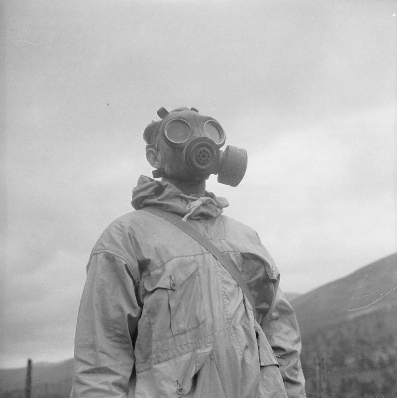
Mountain warfare trooper wearing an assault respirator fitted with side mounted canister whilst training at Glenfeshie, Kincraig, Scotland, 8th August 1942
The designation of the mask can be found painted in white under the chin, however, there are cases where this may have faded over time, making identification impossible. To help with this, the following details explain the components found on each model of respirator.
| Facepiece
Designation |
Rubber Mask | Valve Holder | Harness | Sizes |
|---|---|---|---|---|
| Mk. I | L1 | L1 | L1 & L2 | Small, Normal, Large |
| Mk. IA | L1 | L2 | L1 & L2 | Small, Normal, Large |
| Mk. II | L2 | L1 | L1 & L2 | Normal |
| Mk. II Derm | L2 | L1 | L2 | Normal |
| Mk. IIA | L2 | L2 | L1 & L2 | Normal |
| Mk. IIA Derm | L2 DERM | L2 | L2 | Normal |
| Mk. III | L1 | L3 | L1 & L2 | Small, Normal, Large |
| Mk. IIIA | L2 | L3 | L1 & L2 | Normal |
| Mk. IIIA Derm | L2 DERM | L3 | L2 | Normal |
| Mk. IV | L3 | L2 | L1 & L2 | S, N, L |
| Mk. IV L.H. | L3 LH | L2 | L1 & L2 | S, N, L |
| Mk. IV Derm | L3 DERM | L2 | L2 | S, N, L |
| Mk. IV L.H Derm | L3 LH DERM | L2 | L2 | S, N, L |
| Mk. V | L3 | L3 | L1 & L2 | S, N, L |
| Mk. V L.H. | L3 LH | L3 | L1 & L2 | S, N, L |
| Mk. V Derm | L3 DERM | L3 | L2 | S, N, L |
| Mk. V L.H. Derm | L3 LH DERM | L3 | L2 | S, N, L |

Designations of masks can be found printed under the chin unless faded or never issued
Notes:
- Masks marked "DERM" used special rubber blends for those who suffered from various skin conditions. This likely is also the reason the L1 harnesses were not used due to the rubber content on them.
- Masks marked "L.H." had right-mounted filter ports for left-handed shooters
- Though not marked, some respirators stamped with a red dot on the supporting fabric are made from a synthetic rubber as opposed to the standard black rubber.
Photographic Examples of Each Light Respirator Facepiece
In addition to the table above, here are photographic examples of each of the eight facepieces used during the war. Keep in mind, many are difficult to distinguish from one another, so it is best to consult the table before assuming the designation of your example.
")
")
")
")
")
")
")
")
Components
Mask, Rubber (faceblank)
The primary component of any mask is the rubber mask, which is typically referred to as the faceblank outside of Great Britain. There were three masks issued during the war, one of which carried on its service until the 60s, perhaps even 70s. These masks are designated L1, L2 & L3. Each can be identified by the features below or by the designation which can be found bossed into the rubber inside the mask where the nose would be.
L1 "CDR-Type" Rubber Mask:
Sizes: Small, Normal, Large
Variants: None
Usage: Mk. I, Mk. IA, Mk. III
Originally known as the "CDR-Type Mask", the L1 mask bears most resemblance to the British Civilian Duty Respirator in that it is constructor from thick-cut rubber and features a triangle-shaped boss on the nose which would have served as a mount for the flutter valve of the Civilian Duty Respirator. This mask features a single support beam inside the mask located above and between the eye-pieces.
")
")
L2 "No. 5-Type" Rubber Mask:
Sizes: Normal
Variants: DERM (Dermatitis-friendly rubber)
Usage: Mk. II, Mk. IIA, Mk. IIIA
Originally known as the "No. 5-Type Mask", the L2 mask features a flat-nose and thinner-cut rubber, more-so like the Mk. V Anti-Gas, Respirator (GSR). These masks were made only in normal sizes which is why the L1 mask continued service for a while until the L3 rubber mask began to replace them. The L2 also varies from the L1 in that it features two supporting beams at the top of the mask's interior. These masks are the most common as the majority of Danish M/45E export masks used these masks.
")
L3 "Thin-Type" Rubber Mask:
Sizes: S, N, L
Variants: DERM (Dermatitis-friendly rubber), L.H. (Left-Handed)
Usage: Mk. IV, Mk. V (later Mk. 6 and 7)
The L3 mask mostly resembles the L2 in that it features the flat "No. 5-Type" nose but uses much less rubber to create a thinner mask. This type was originally known as the "Thin-Type Mask" but, whilst being much thinner than the L2, it retained its sturdiness by using an improved blend of rubber which would retain its shape better.
These masks also feature some further improvements in that they use both a canvas reinforcement and an extra horizontal support bar around the nose area to keep the mask in better shape despite the increased flexibility. The L3 was also available in small, medium and large, simply marked with the letters S, N and L, rendering the L1 obsolete.
This mask was favoured so much that the British Armed Forces continued to use it up until Service Respirator No. 6 transition. The L3 mask can be found on Respirators, Anti-Gas, Light Mk. IV and V, however, it is worth noting that a slightly refined variant of the L3 mask, seemingly referred to as the L3-4 or L3/4, was used on Respirators Mk. 6 and 7 after the war. The Light Respirator Mk. IV and V Respirators and their variants were the only ones known to have used these masks during the wartime by 1944. The earliest found example is dated April 1944 yet documents suggest these masks began production as early as April 1943.

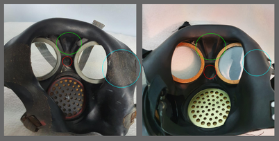
1940s and 1950s L3 Rubber Masks Compared on Mks. V and 6 Light Respirators
Telling the WWII Period L3 Mask apart from the Post-War "L3-4" can be difficult to the untrained eye due to the shapes described in technical manuals being identical, such as the additional horizontal support beam, support fabric between the lenses, the use of single letter-size designations, etc. However, there are some minor differences which can be used to identify between the two (also see the image for colour references below). The differences are as follows:
- Red: The wartime L3 simply says "L3" between the lenses whereas the post-war variants are labelled "L3" with a line underneath and a "4" beneath the line.
- Blue: The Support fabric on wartime L3 masks is slightly visible and is completely coated on post-war masks.
- Green: The two vertical support beams were much more "squared" in the wartime mask and were moulded much smoother, almost rounded, post-war.
- Aside from this, there is a clear difference in rubber quality with the wartime masks feeling somewhat more firm, however, this could differ between manufacturer. Also, bear in mind that the above example is synthetic rubber.
- Underneath the chin, wartime masks should be marked "Mk. IV", "Mk. 4", "Mk. V" or "Mk. 5" whereas post-war masks will be marked "GD" + a date and then either the designation "Mk. 6 or Mk. 7".
The primary difference between the two seems to be that the wartime variant exclusively used the "stiff-type" synthetic rubber blend, as a means of compensation for the thinner rubber. The post-war type went back to using the mostly natural reclaimed black rubber mix, making the mask a lot smoother and a lot more flexible.
")
Rubber Type
The rubber type refers to the composition of the rubber or synthetic rubber used during the making of the masks. There were three variants during the war, the standard black rubber, the synthetic and the "DERM" blend. These three were used on all three mask variants.
DERM-Type Rubber:
The majority of masks use the typical black rubber however, due to some soldiers experiencing dermatitis from the rubber, specialised masks were made from a brown-ish coloured rubber marked "DERM". This rubber variant was initially introduced with the Mk. V General Service Respirator and can be found available with the Light rubber masks No. L2 and L3.
Special Synthetic "Stiff-Type" Rubber:

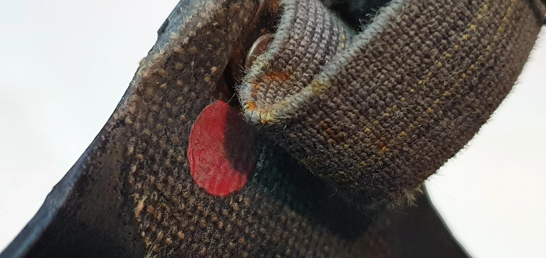
Red marking indicating the use of Synthetic Rubber on a Light Respirator Mk. V
Whilst most Light Anti-Gas Respirators were composed of Black Rubber or, of course, the special variant for dermatitis, some were actually made of an unnamed synthetic rubber (to be tested). Variants using this special blend would be marked with a red dot on the support fabric of the mask. This would typically be located around the six harness connection sites around the mask, however, it is documented that some L3 masks would have the red dot stamped into the support fabric located between the eyepieces.
Synthetic rubber is much stiffer than the typical blend and was designed to help better keep the shape of the mask when using less rubber, especially when using the L3 mould which used a lot less rubber than the L1 and L2 types. However, it should be noted that L2 masks have been created using this blend too.
Holder, Valve, Assembly & Valve, Outlet
One of the largest misconceptions about the Light Anti-Gas series was that the Valve Holder was the identifying part of the mask. Whilst they do somewhat sync up, there are examples of Mk. I masks with L2 Valve Holders and Mk. II masks with L1 Valve Holders. There were, as is commonly known, only three types of Valve Holder but there were also two types of Outlet Valve. The first outlet valve was used in the L1 and L2 Valve Holders. The L1 Outlet Valve was comprised of rubber whilst its counterpart, the L2 Outlet Valve, was made of a translucent material of some kind. This type was used in the L3 Valve Holders.

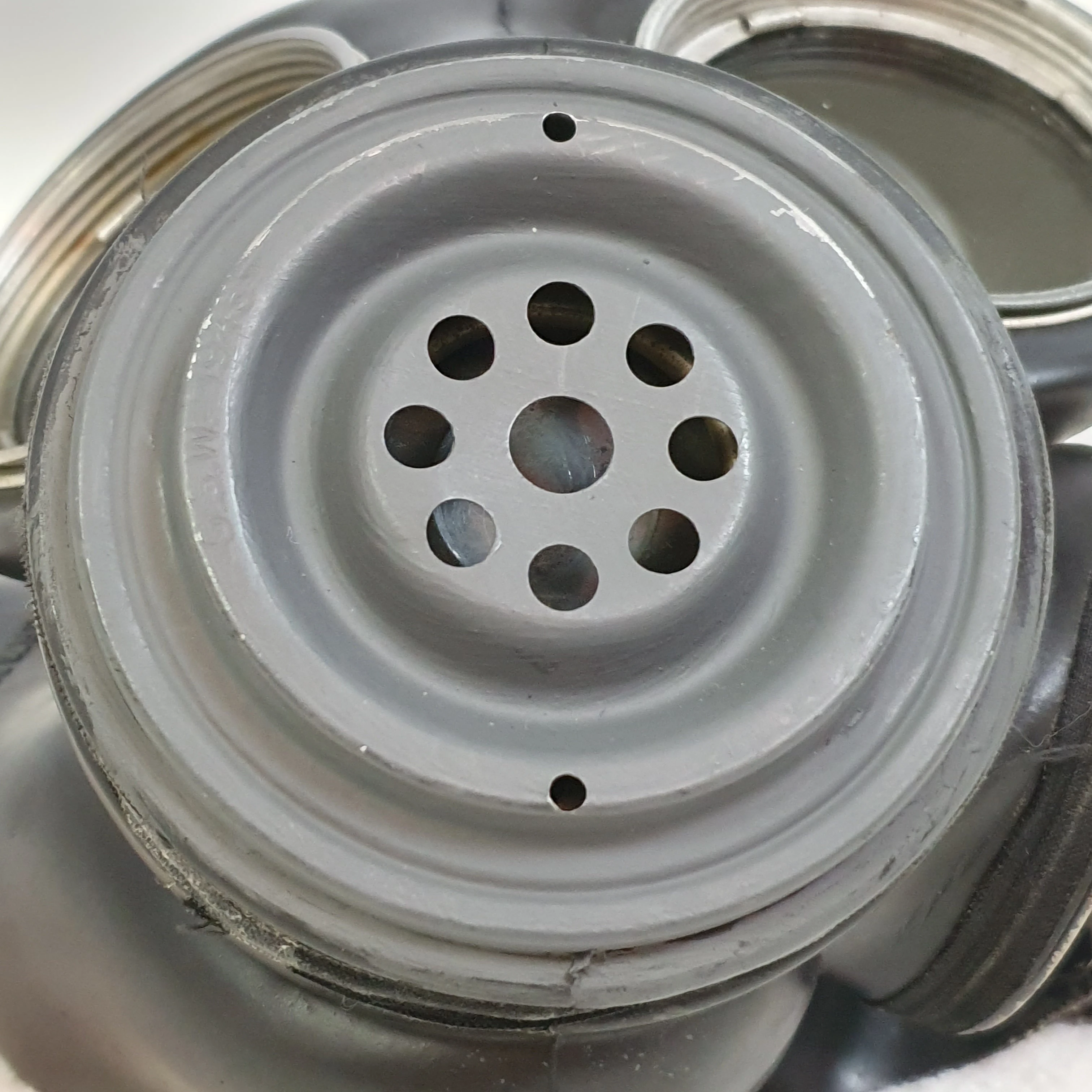
L1 Valve Holder
L1 Valve Holder:
The L1 Valve Holder was designed in 1941. It can be found on Mks. I and II Light Anti-Gas Respirators and also the Mk. I and II Canadian Light Anti-Gas Respirators. The British type can be identified by the marking "L1" around the drainage tract whereas the Canadian type will state the manufacturer (such as C.C.C.) and the year of manufacture. The L1 Valve Holder itself can be identified by the thin drainage tracket, crater and then mound in the centre of this crater.
The L1 Valve Holder Assembly consists of the L1 Valve Holder Body (front-plate) and Seating (back-plate), the L1 Outlet Valve and the Checkplate to keep the valve in position.
Usage: Mk. I, Mk. II

L2 Valve Holder
L2 Valve Holder:

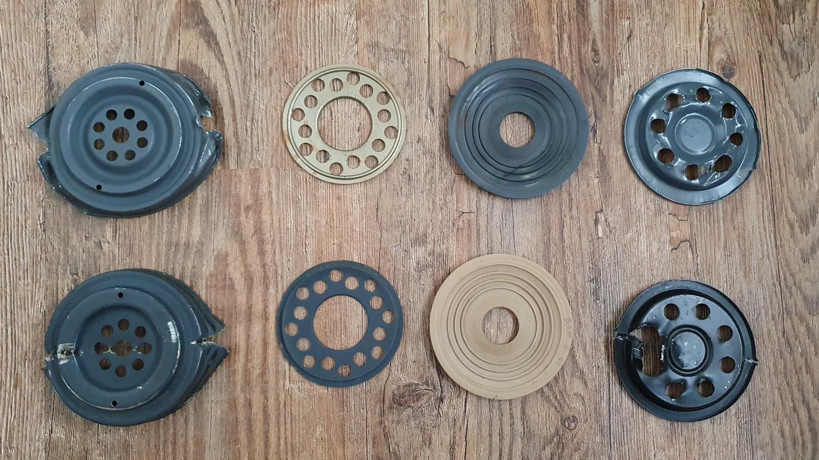
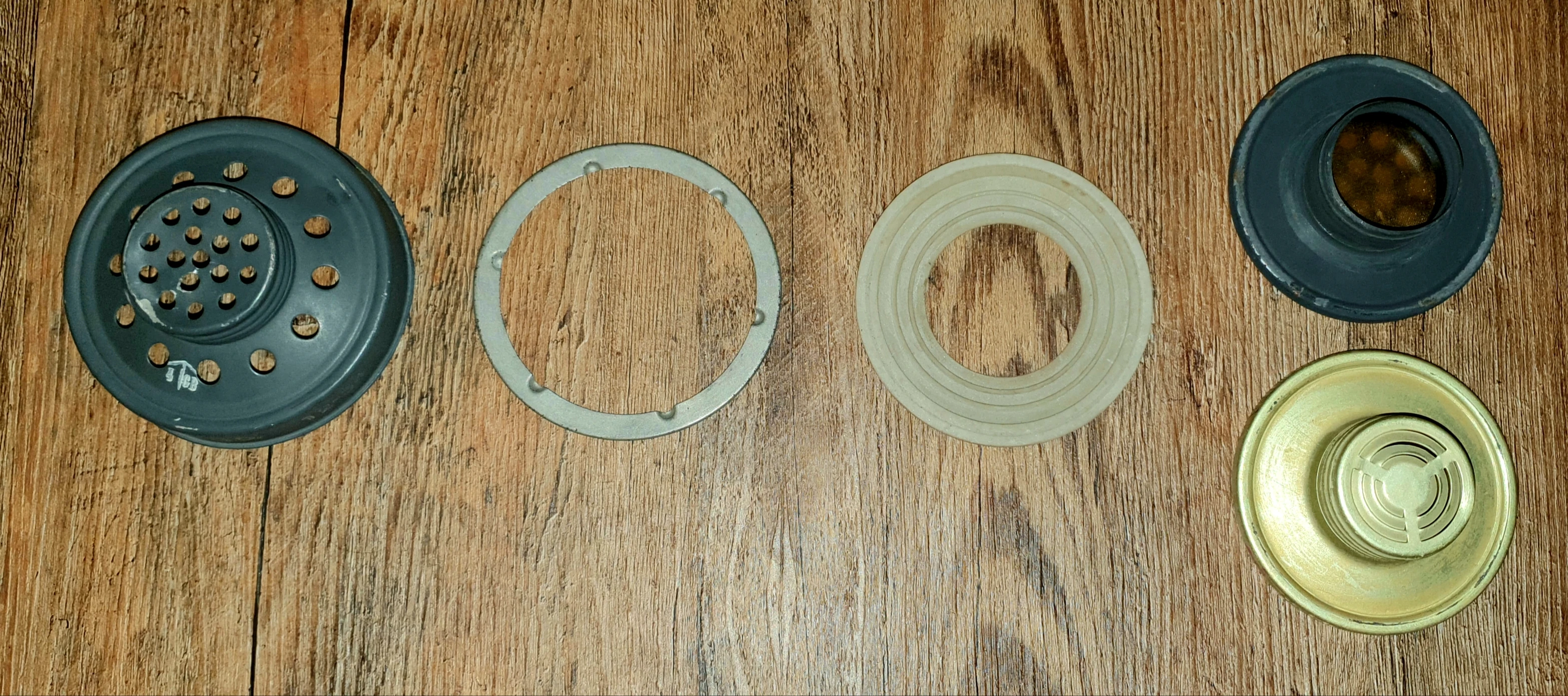
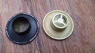
L1 & L2 Valve Holders Disassembled and Compared
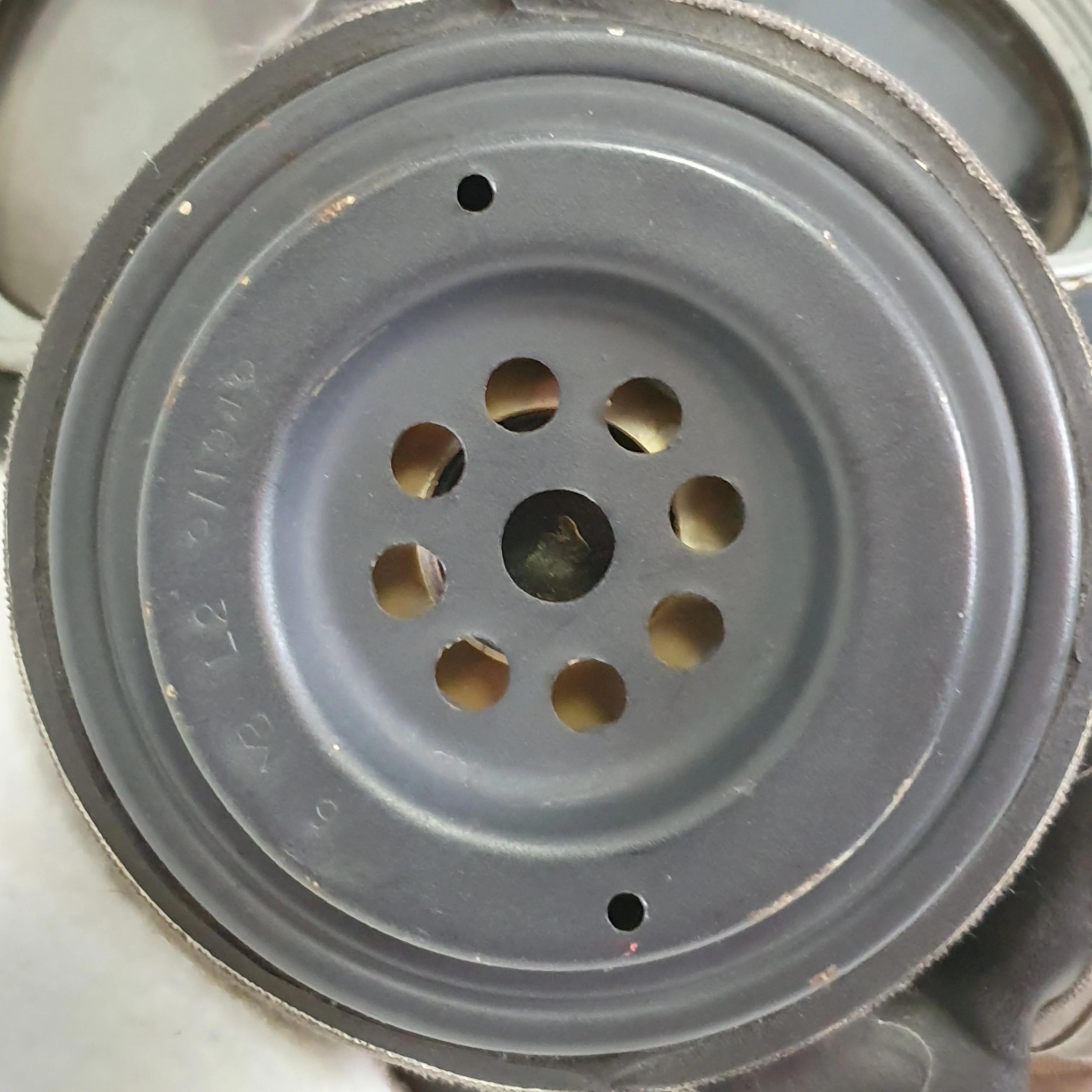
The L2 Valve Holder was designed to replace the L1 Valve Holder, turning facepieces designated Mks. I and II into Mks. IA and IIA. The L2 Valve Holder can be identified by the thick drainage tract, stamped with "L2", the initials of the manufacturer and the date, and by the lack of mound in the crater area.
The L2, when compared to the L1, is essentially the same, however, the L2 Valve Holder enjoys a much more "flat" construction due to the shape of the Body whereas the Seating and even Checkplate of the L1 are a little more dynamic in shape. The reason behind the advent of the L2 valve holder was that the L1 valve holder did not allow for proper seating of various hand microphones. The L2 was designed to let hand microphones sit inside of the crater and cut out a significant amount of noise when compared to the L1.
The L2 Valve Holder Assembly consists of the L2 Valve Holder Front and Back Plates, the L1 Outlet Valve and a metal diaphragm, slightly flatter than that of the L1, to keep the valve in position.
Here is an image comparing the internals of the L1 and L2 Valve Holders. From left to right, you have the Body, the Checkplate, the L1 Outlet Valve (top one is only grey as it is Canadian but would be tan too), and the Seating.
Disclaimer: As you can see, the Valve Holders have been destroyed to bring you this comparison photo. Please do not damage any more examples as this is all you will ever find inside an L1 or L2 Valve Holder. Also, please note that the L1 example was of Canadian production, hence the difference in colouring. The British L1 would follow the same colour pattern as the L2, again, please so not damage any more examples.
Usage: Mk. IA, Mk. IIA, Mk. IV
L3 Valve Holder:
L3 Valve Holder on a L Mk. IIIA Respirator
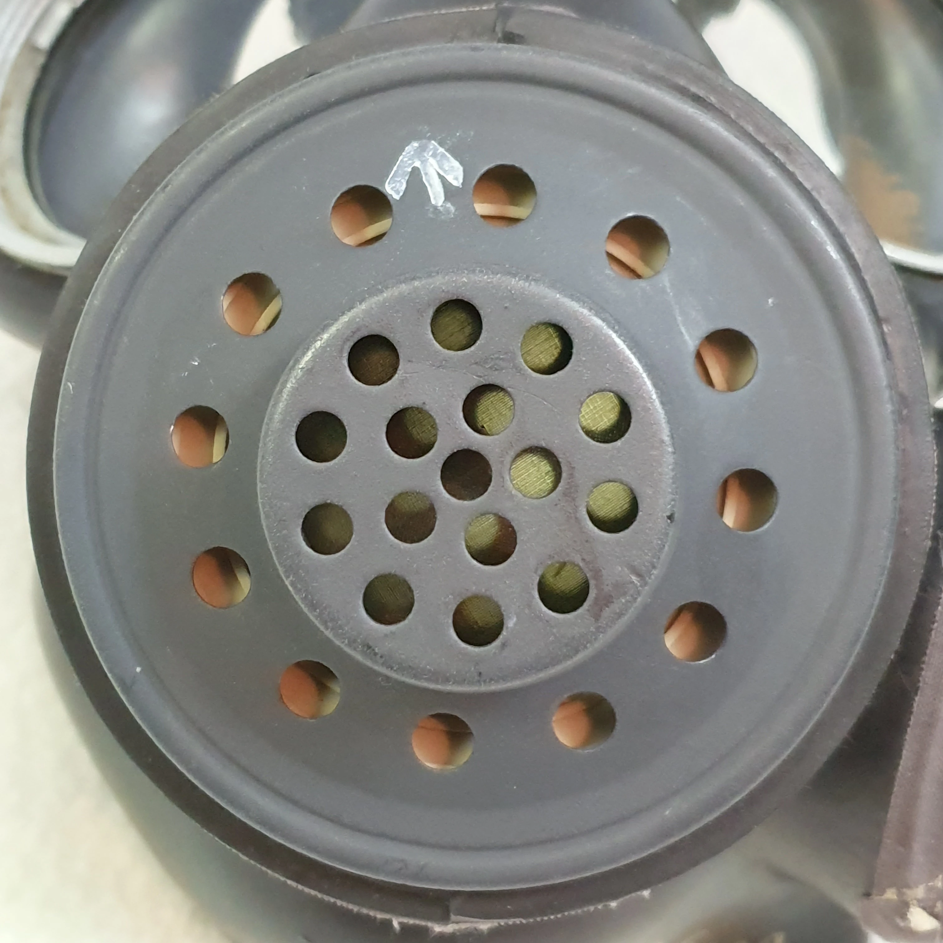
Whilst the L1 and L2 Valve Holders were designed to be little more than their namesake, Light, the L3 went above and beyond and implemented a screw-in speech transmitter unit (voice diaphragm), an upgraded outlet valve and, supposedly, options to help support advanced communications equipment, such as the Tannoy Loudspeaking Apparatus (ALS) of the era using an alternative screw-in insert called the Tannoy-Valve.
The L3 Valve Holder was introduced in 1943, originally referred to as the "Porton Valve", and would see service with the Mk. III and IIIA, then later the Mk. V Light A.G. Respirators. Following the war, this Valve Holder would be modified and would continue to be used with Mks. 6 and 7 facepieces under the new name L5 Mk. 1. The design even influenced the S6 NBC Respirator heavily in regards to the construction and shape of the speech transmitter unit, the front cover of the speech transmitter unit and even the method of exhalation.

L3 Valve Holder broken down
In terms of construction, the L3 Valve Holder is built from the L1 Speech Transmitter, the L2 Outlet Valve, a metal ring to suspend the valve, much like the metal diaphragm did in the L1 and L2, and, of course, the L3 Valve Holder body, itself. Unlike the L1 and L2 Valve Holders, the L3 can be completely disassembled by way of unscrewing the speech transmitter unit from the body and gently easing out the valve and ring.
L1 Speech Transmitter:

1940s-style L1 & 1950s-style L2 Speech Transmitters
During the war, one speech transmitter design was available. This design was eventually designated No. L1 Speech Transmitter. It was made up of 3 parts; a base plate, the main body/threading and an oiled-silk disk (diaphragm).
The speech transmitter functioned well, the only issue with it being the large opening, as displayed in the left example of the photo. This large opening caused great concern, and was likely the reason why most men used respirators fitted with the L2 valve holder. To fix this issue, in the 1950s, a new design was created and designated No. L2 Mk. 1 (right). It differed only in that it featured a grille where there was once an opening. This meant the speech transmitter would be able to be trusted in combat situations without the constant fear of debris repturing the diaphragm.
Mk. IIIA Light Respirator upgraded to meet the requirements of the 1950s
Mk. 6 and 7 Light Respirators, designed and issued in the 1950s, were all fitted with this new type, but also, some Mk. IIIs, IIIAs and Vs had their L1 speech transmitters swapped out for the newer L2 Mk. 1, presumably so that those masks could still continue service with their former owners to, of course, save a lot of money.
Here is an example of a Mk. IIIA fitted with the post-war L2 Mk. 1 speech transmitter for post-war issue:
As there is a lot of similarity with the components used post war, and even cases of wartime and post-war components being mixed, please note the following:
- Speech Transmitter can be considered synonymous with "voice diaphragm" or any other term used to describe a respirator component designed to enhance the clarity of speech by means of a vibrating sheet of some kind.
- No. L2 speech transmitters were designed in the 1950s, some were installed onto wartime masks, but this only happened in the 1950s. No L2 speech transmitters existed in the 1940s.
- Post-war L3-style valve holders are actually called L5 valve holders and are made of non-ferrous metal. L3 valve holders are magnetic, L5s are not.
Usage: Mk. III, Mk. IIIA, Mk. V
Headharness
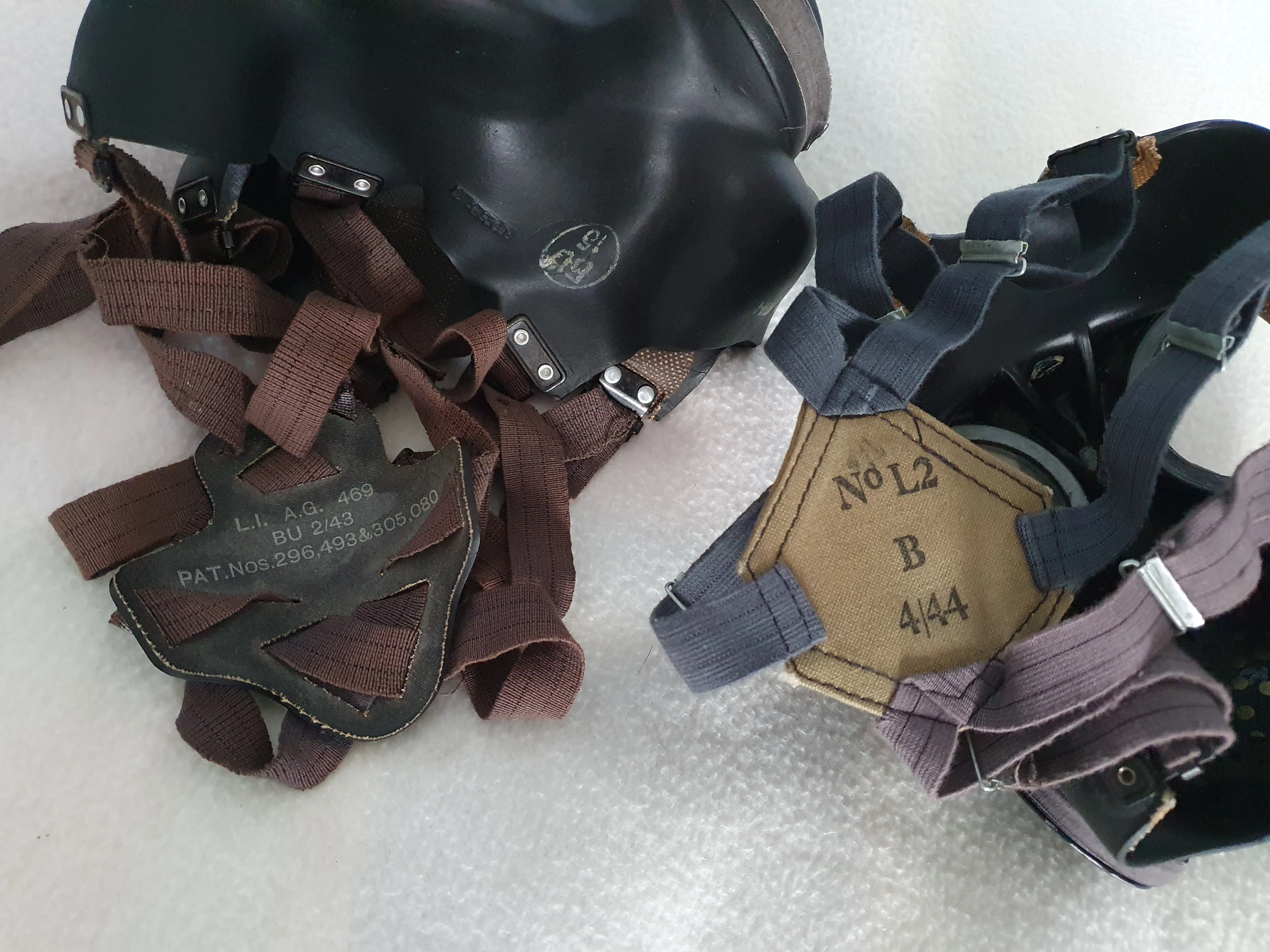
L1 & L2 Harnesses
There were two harnesses used on Light Anti-Gas Respirators during the war, Nos. L1 and L2. These two harnesses are often confused with the No. 4 Mk. III and No. 4 Mk. II headharnesses, used earlier in the war and on the homefront. The difference between the two similar-looking duos is that the L models used a slightly different elastic material to the No. 4s seen on the Civilian Duty and General Service Respirators, supposedly making them stronger.
The L1 harness features a complex weave of straps through a rubberised back-plate, known previously as the Mk. III head-pad when applied to GS Respirators as headharness No. 4 Mk. III. The L2, on the other hand, simplifies the design by connecting adjustable elastics to a hexagonal head-pad, previously known as head-pad Mk. II. Both were used on Respirators, Anti-Gas Light Mk. I all through to Mk. V. The L1 headharnesses were never used on DERM-type masks due to the fact that the rubber on the head-pad could have also caused irritation when compared to the L2's rubber-free construction.
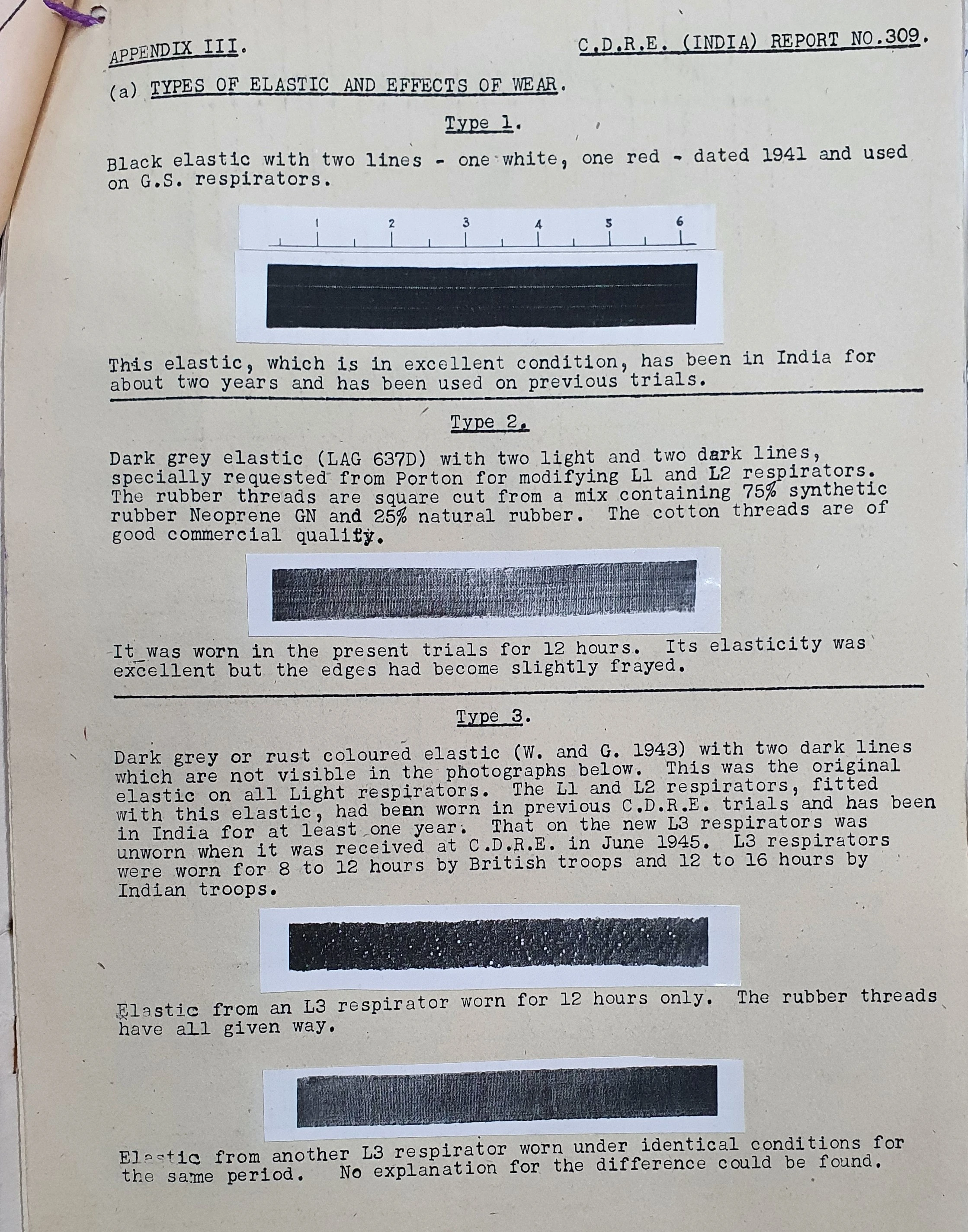
Part of the Special Light Respirator documentation photographed by Baroque4Days
Referring back to the earlier point made on the straps or elastics used on the head-pads, three types of elastics were used during the war, Types 1, 2 and 3, with only Types 2 and 3 being used on the Light Respirator. Officially, these latter two types are known as "Type L webbing". As mentioned earlier, the idea behind transforming the earlier No. 4 Mks. II and III harnesses to Nos. L1 and L2 was to improve the elastics whilst retaining the type styles of head-pad. Type 1 Elastic was used with No. 4 Mks. I - IV and was fitted to G.S. Respirators only aside from some earlier Light Respirators trialled in India. Whilst credited for its comfort and longevity, the Type 1 elastic likely not able to deal with the added weight to the facepiece and thus, a few stronger elastic material was required, sometimes even referred to as "webbing".
The type identified as Type 3 by Porton was the first type official used with the Light A.G. Respirator and was known to often break within were hours of issue. This type can be identified by the rust-grey colour of the elastic with two black lines running down the middle. Type 2, the later type, can be identified by its grey-blue tone and was credited as a much stronger material which, at worst, would fray around the edges but never lose elasticity or break entirely. As mentioned earlier, both Type 2 and 3 were officially referred to as Type L webbing, and Types 1 to 3 were merely assignments given to the three strap types during the trials.
Kit Contents
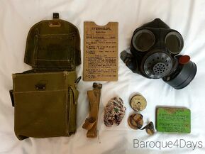
The Light Anti-Gas Respirator kit is comprised of the Respirator Facepiece and Light Container, 1 pair of Sealing Plugs, 1 Tin of Anti-Gas Ointment, 1 Carton of Anti-Gas Eyeshields, 1 Anti-Dimming Cloth, 1 Cleaning Cloth and 1 bundle of Cotton Waste weighing roughly 1 oz. This kit is stored in Light Respirator Haversacks L1 Mk. I or L1 Mk. II.
It is also listed on a soldier's Anti-Gas Inspection Report that the soldier would also have been issued with an additional tin of No. 5 Ointment, two identity disks, an Anti-Gas booklet (shown in the image for this section), "Detectors, Gas, Ground" and the Inspection Report itself. In the report, soldiers are instructed to carry both the booklet and report on them in the haversack at all times.
There has been a misconception that the two side pockets were both used to store Ointment. This, however, was not the case, as explained in the Gas Training Manual of either 1942 or 1943.
Respirator Kit Examples

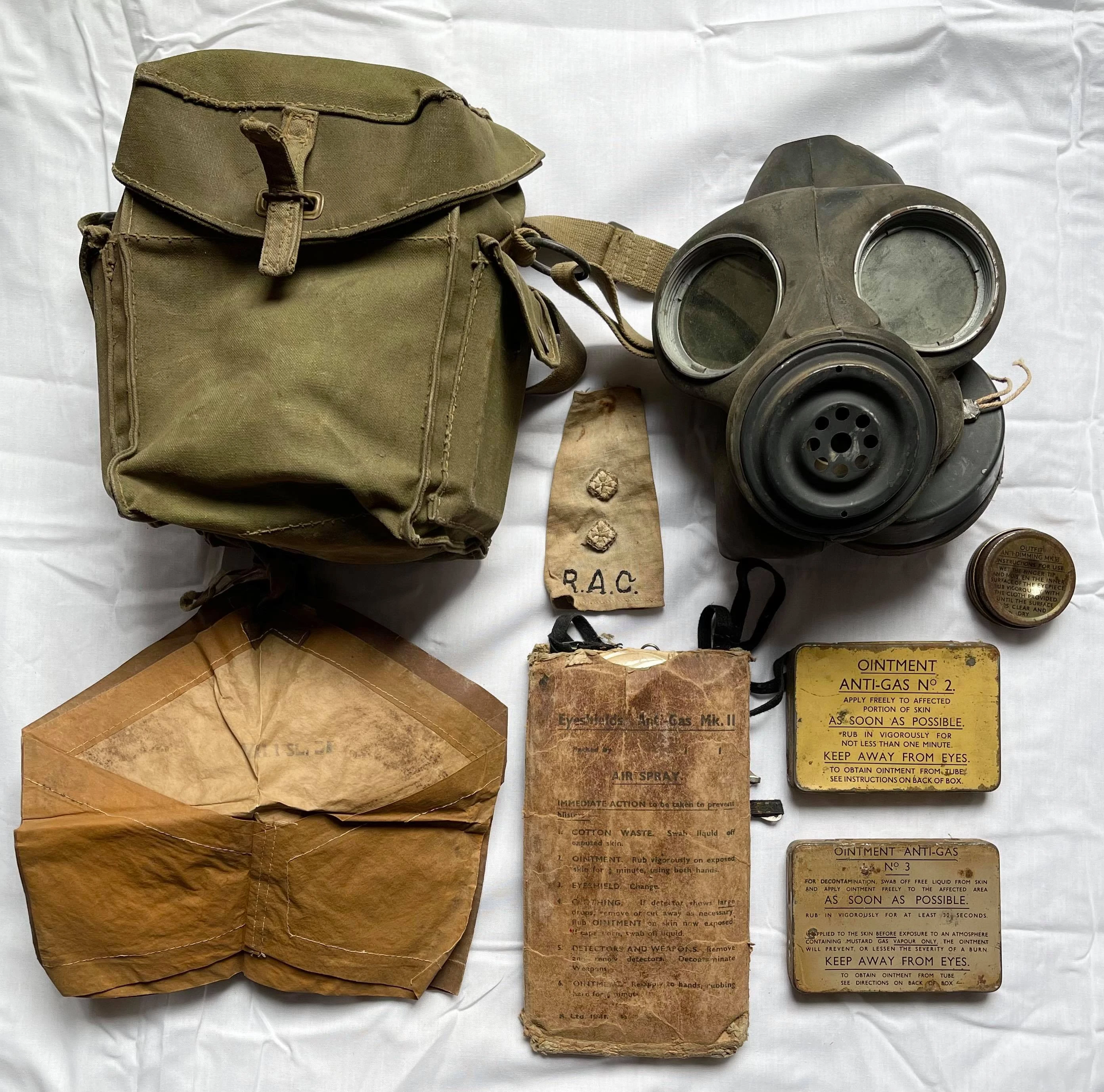
Mk. I Light Respirator & 1942 early issue kit from the collection of J. R. Valentine.
Example contents of an early service (1942) kit as follows:
- Respirator, Anti-Gas, Light, Mk. I or II Facepiece (Mk. I photographed)
- Container, Light, Mk. I or II & Plugs, Sealing, Mk. I (Mk. I photographed)
- Outfit, Anti-Dimming, Mk. VI (rarely Mk. V)
- Ointment, Anti-Gas, No. 2, 3 or 5
- Eyeshields, Anti-Gas, Mk. II
- Waste, Cotton, 1oz
- Cleaning Cloth
- 2x Pairs of Detectors, Sleeve
- Haversack, Respirator, Light, No. L1 Mk. I or L1 Mk. II
Example contents of a standard service (1943 - 45) kit as follows:

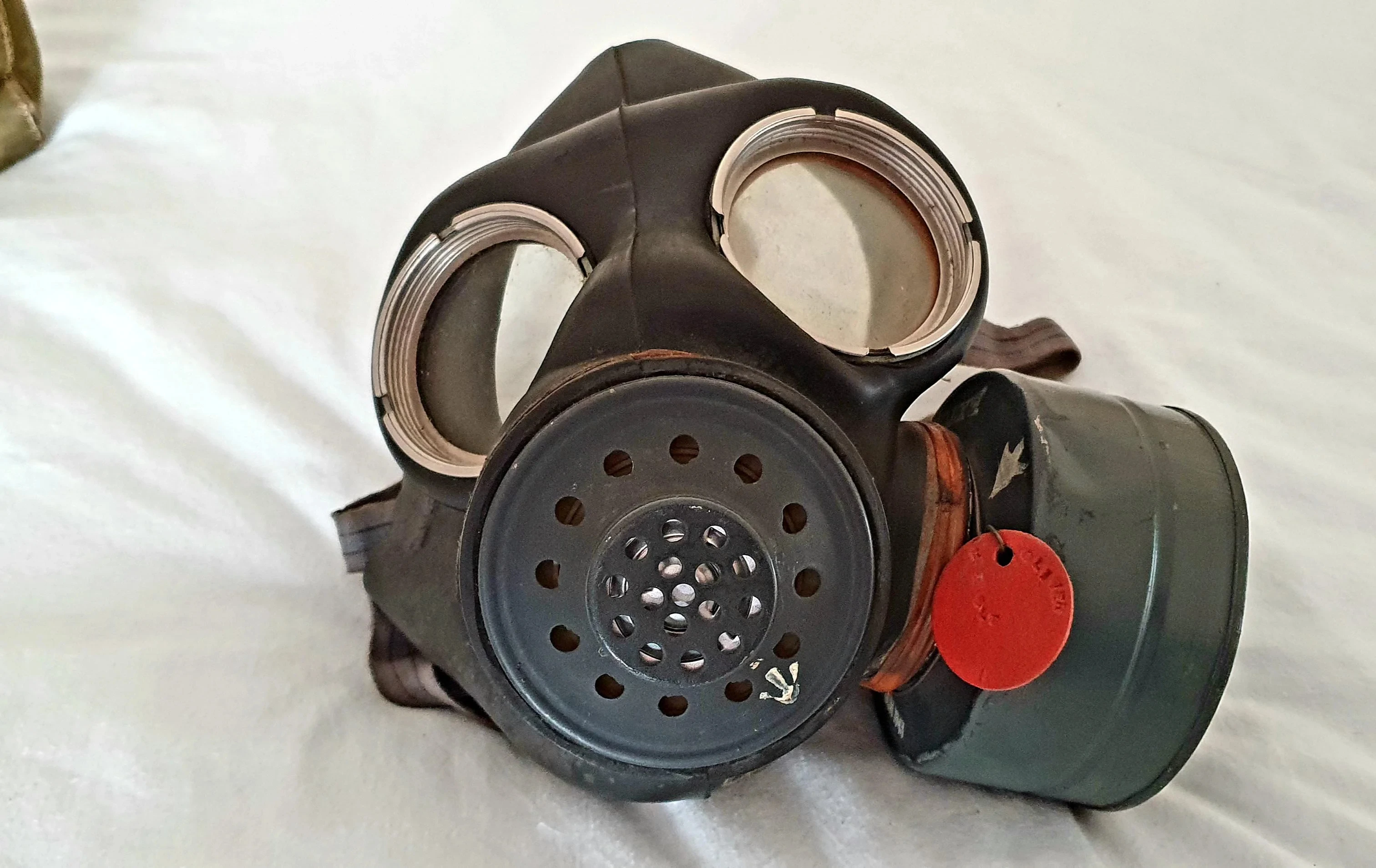
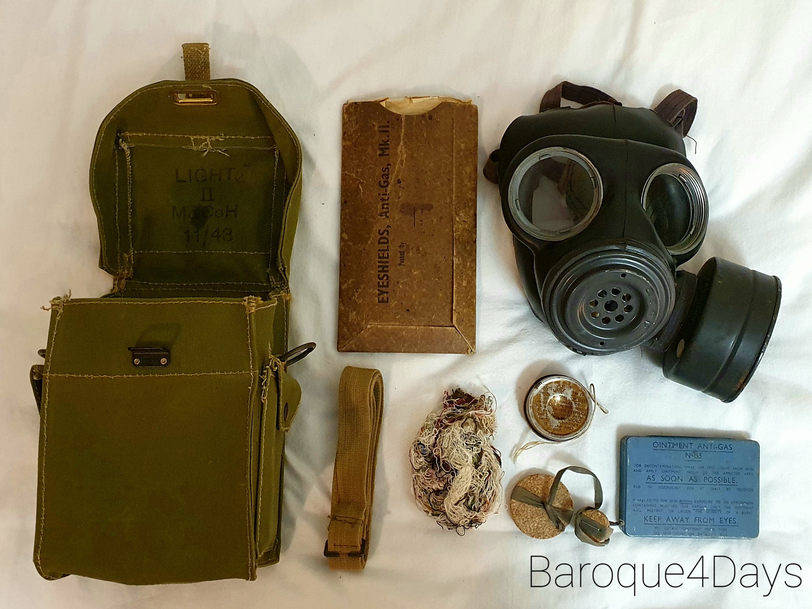
Mk. IIA Light Anti-Gas Respirator & 1943-45 standard service kit
- Respirator, Anti-Gas, Light, Mk. IA or IIA Facepiece (Mk. IIA photographed)
- Container, Light, Mk. II & Plugs, Sealing, Mk. I
- Outfit, Anti-Dimming, Mk. VI (Impregnated Cloth)
- Ointment, Anti-Gas, No. 3 or 5 (rarely No. 2)
- Eyeshields, Anti-Gas, Mk. II
- Waste, Cotton, 1oz
- Cleaning Cloth
- 2x Pairs of Detectors, Sleeve
- Haversack, Respirator, Light, No. L1 Mk. I or L1 Mk. II
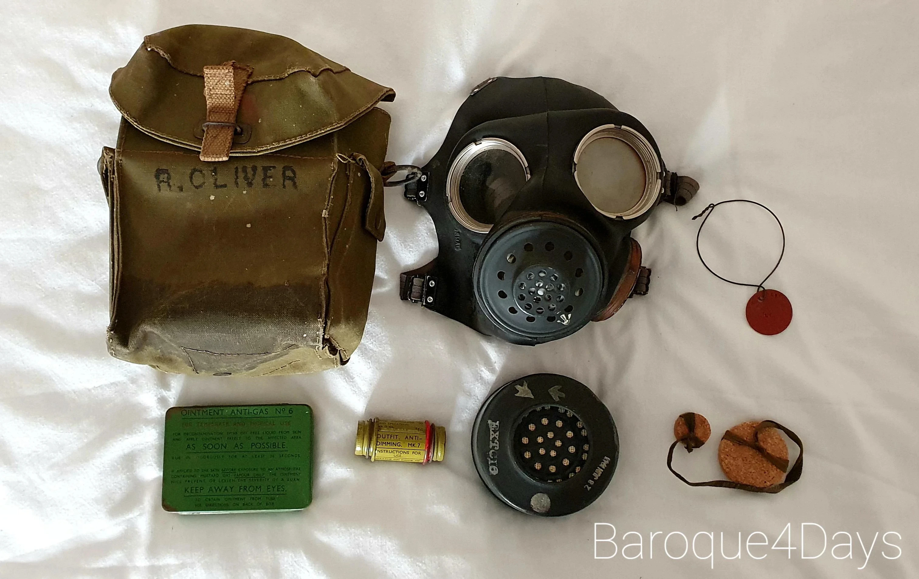
Example contents of an 21st Army Group, Royal Singals & Regimental Signallers issue (1943 - 45) kit as follows:

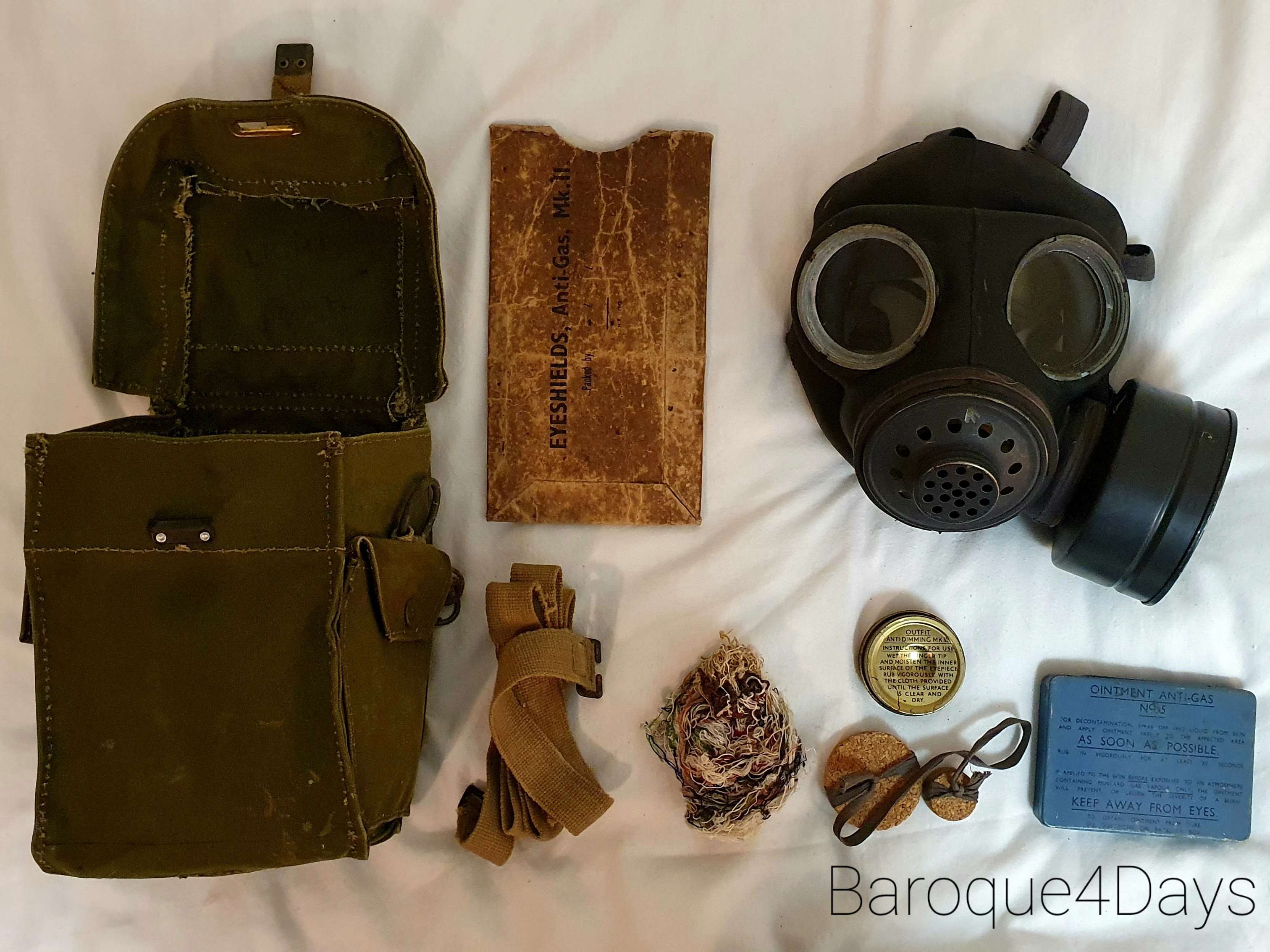
Mk. IIIA Light Anti-Gas Respirator & 1943-45 specialist-issue kit
- Respirator, Anti-Gas, Light, Mk. III or IIIA Facepiece (Mk. IIIA photographed)
- Container, Light, Mk. II & Plugs, Sealing, Mk. I
- Outfit, Anti-Dimming, Mk. VI (Impregnated Cloth)
- Ointment, Anti-Gas, No. 5 or 6 (No. 6 photographed)
- Eyeshields, Anti-Gas, Mk. III
- Waste, Cotton, 1oz
- Cleaning Cloth
- 2x Pairs of Detectors, Sleeve
- Haversack, Respirator, Light, No. L1 Mk. II
Example contents of a late-production (1944-45) standard service kit as follows:

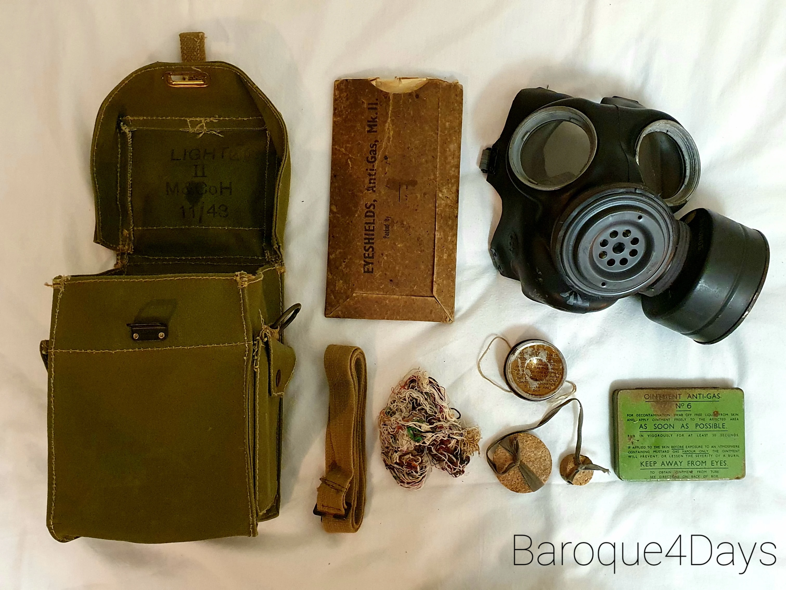
Mk. IV Light Anti-Gas Respirator & late-war standard service kit
- Respirator, Anti-Gas, Light, Mk. IV Facepiece
- Container, Light, Mk. II & Plugs, Sealing Mk. I
- Outfit, Anti-Dimming, Mk. VI (Impregnated Cloth)
- Ointment, Anti-Gas, No. 6
- Eyeshields, Anti-Gas, Mk. III
- Waste, Cotton, 1oz
- Cleaning Cloth
- 2x Pairs of Detectors, Sleeve
- Haversack, Respirator, Light, No. L1 Mk. II
Example contents of a late-production, comms-user-issue, RN issue (1944-45), kit as follows:

Mk. V Light Anti-Gas Respirator & late-war kit seemingly only issued to those less likely to be in combat, especially Royal Navy
- Respirator, Anti-Gas, Light, Mk. V Facepiece
- Container, Light, Mk. II & Plugs, Sealing Mk. I
- Outfit, Anti-Dimming, Mk. VI (Impregnated Cloth)
- Ointment, Anti-Gas, No. 6
- Eyeshields, Anti-Gas, Mk. III
- Waste, Cotton, 1oz
- Cleaning Cloth
- 2x Pairs of Detectors, Sleeve
- Haversack, Respirator, Light, No. L1 Mk. II
Example contents of an upgraded speech transmitter model for 1950s standard service issue, kit as follows:

Mk. IIIA Light Anti-Gas Respirator & post-war standard service kit. Issued alongside Mk. 6 Light Respirators.
- Respirator, Anti-Gas, Light, Mk. III, IIIA or V Facepiece (Mk. IIIA photographed)
- Container, Light, Mk. II & Plugs, Sealing Mk. I
- Outfit, Anti-Dimming, Mk. VII
- Ointment, Anti-Gas, No. 6 "for temperate and tropical use"
- Eyeshields, Anti-Gas, Mk. I (re-packed 1950s)
- Waste, Cotton, 1oz
- Cleaning Cloth
- 2x Pairs of Detectors, Sleeve
- Haversack, Respirator, Light, No. L1 Mk. II or No. L1 Mk. II/I (L1 Mk. II photographed)
Container, Light
The Light Container included is comprised of three layers, one being charcoal and the other two being either fully resin-impregnated wool or fabric or, they would contain one of each. It is worth noting that NO Light Container contained Asbestos. When not in use, two pieces of cork, designated Plugs, Sealing Mk. I, attached by fabric, would be placed in the hole at the bottom of the filter and the other would sit inside the mask in the intake-area to help prevent water entering the filter whilst in transit.
There were two types of container used on the Light Respirators during the war, the Light Container Mk. I and Mk. II. Both containers should have L1/L2, No. 1/2 or Light I/II written or engraved on/into the top and base of the container. The containers do vary a little in shape.
What made the Light Container special, aside from the obvious change in direction of respirator design, was its use of the new filter material, resin-impregnated wool as opposed to asbestos-impregnated wool. This new mix was developed during the arsine scare as superior particulate filtration was believed to have been a good counter measure to the threat alongside lime permanganate.


Photo from the collection of J. R. Valentine
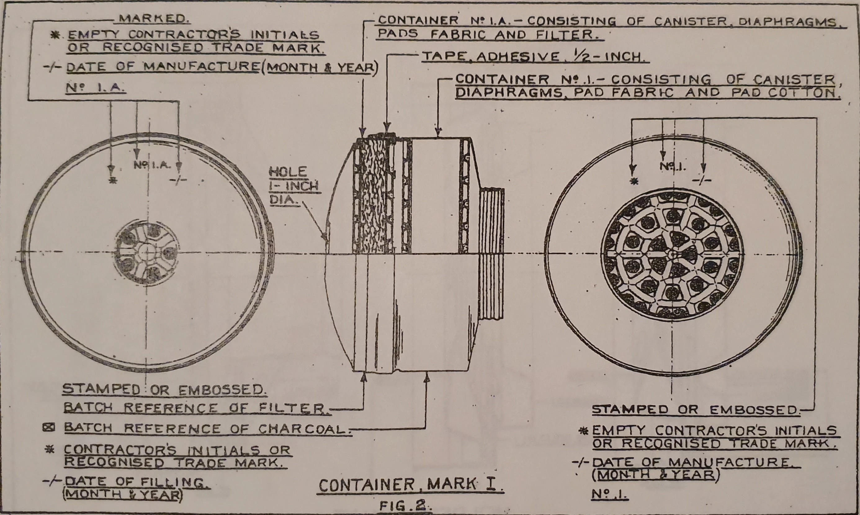
Light Container Mk. I:
Light Container Mk. I Diagram
The Mk. I Light Container was developed through 1941 and then issued at the very end of 1941 with the Mk. I and until late 1942 with the Mk. II Light Respirator. This container was an ad hoc solution to the need for a new container for the newly designed respirator. The intention was for the container to be issued where needed whilst work on the Mk. II container would be undertaken. This is what happened, and it was eventually put to those responsible for the repair of respirators that all Mk. I containers hsould be disposed of and replaced with Mk. IIs.
The container is made up of two parts, also designated as containers. Containers No. 1 and 1A were filled and then taped together to form the Mk. I Light Container. Container No. 1 was the larger of the two sub-containers. It consisted of the No. 1 canister, fabric pads, cotton pads, diaphragms and the charcoal mix. Container No. 1A consisted of the No. 1A canister, fabric pads, diaphragms and the resin-wool filter mixture.
The difference between the back plate seen on the Mk. II container and the base of the No. 1A canister was the lip. As Mk. II containers feature a recessed back plate, pressed into the drum of canister No. 2, there is a visible lip around the bottom rim of the container. This does not appear on the Mk. I as the lower-third of the container is, of course, a seprate container itself (No. 1A). Aside from this, the tape, or marks where tape used to be, can also be used to identify this container.
One of the key differences actually is in the markings. As explained in the diagram, and shown in the photo, the Mk. I container features markings on both of the sub-containers to indicate which is which, along with dates of manufacture. In addition to this, the side of the No. 1 container features information on the construction date, the batch reference of the charcoal and information on the contractor responsible for its creation.
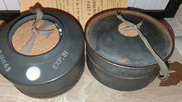
Light Container Mk. II:

Light Containers Mk. II
The Mk. I design was something of an ad hoc configuration made to quickly get an anti-gas container issued with the Mk. I respirators. The Mk. II design was already in the minds of those involved with the creation of the Mk. I in that it should be filled entirely into a single canister with a back plate closing it off.
The contents of the filter is exactly the same as the Mk. I and the general layout of the filter contents remains unchanged. The Mk. II can be identified, aside from the lack of tape, by a lip at the base of the container, meaning the plate on the bottom would sit recessed inside the body.
Light Container Contents from bottom to top:
- Either the No. I.A. Canister (L Mk. I) or the Mk. II's back plate (L Mk. II)
- Diaphragm
- Either Pad, Fabric (L Mk. I) or Pads, Fabric & Cotton (L Mk. II)
- Filter (resin-impregnated wool)
- Either Pad, Fabric (L Mk. I) or Pads, Fabric & Cotton (L Mk. II)
- Diaphragm
- Pads, Fabric & Cotton
- Charcoal
- Pads, Fabric & Cotton
- Diaphragm
- Either No. I. Canister (L Mk. I) or the Mk. II's No. II. Canister (L Mk. II)
In 1943, the Mk. II Container saw an upgrade which would see it protected better against prussic acid (hydrogen cyanide), containers with this upgraded marked, on the connical face to the top of the container, with a white dot. In August 1944, a further upgrade to the charcoal mix was introduced to afford better protection against cyanogen chloride.
Haversack, Respirator, Light
Light Haversack No. L1 Mk. I:
Content (early variants without the pocket)
Light Haversack No. L1 Mk. II:
Content
Light Haversack No. L1 Mk. III:
Content
Light Haversack No. L2 Mk. I:
Content
Additional Kit
Aside from the Facepiece, Container and Haversack, the Light Anti-Gas Respirator was issued with a tin of 8 tubes of Anti-Gas Ointment, a Mk. VI Anti-Dimming Outfit Cloth, a Cleaning Cloth and 1oz of Cotton Waste.
At first, the 1941-type No. 3 and 1942-type No. 5 Anti-Gas Ointments were used, however, later into the war, No. 6 tins and even Tropical Variants of No. 6 were used from 1944. The Ointment would be found inside the right pocket of the haversack with the cotton waste bundle, included to soak up droplets on skin and equipment, stored opposite.
The Anti-Dimming outfit would be stored inside a small gold-coloured tin and inserted inside the pocket at the bottom of the haversack. The cleaning cloth would then be folded to an appropriate size and stored on top of this, almost serving as a cushion for the respirator facepiece.
Finally, an Anti-Gas Booklet would be stored inside the haversack to give soldiers some basic reminders on how to perform the various parts of Gas Drill described in the Gas Training booklet.
History and Use
Basic History of the Eight Marks
To understand the full history of this respirator during wartime, do continue reading the below sections, however, if you wish for a simple overview of when each model was made and roughly where they were issued, please refer to the following table.
| Facepiece | Designed | Issued | Users |
|---|---|---|---|
| Mk. I | 1941, December | 1942 | Special assault troops, AFV Crewmen |
| Mk. II | 1942, Early | 1942 | Special assault troops, AFV Crewmen |
| Mk. IA & IIA | 1942, Late | 1943 - 1950s | General Service |
| Mk. III & IIIA | 1943 | 1944 - 1950s | 21st Army Group, Royal Signals, Regimental Signallers |
| Mk. IV | 1942 (theoretical), 1944 (actual) | 1944 - 1950s | Unknown, assumed successor of IA and IIA if replacement needed |
| Mk. V | 1943 (theoretical), 1944 (actual) | 1944 - 1950s | Royal Navy, assumed successor of III and IIIA if replacement needed |
Deisgn, Production & Trials of the Special Light Respirator
Coming soon...
Adoption of the Mk. I Design
Coming soon...
Talks of a Mk. II Respirator
Coming soon...
Deisgn & Production of the Mk. II Light Respirator
Coming soon...
Comparing the Mk. I & II Designs
Coming soon...
Troop Trials and Early Issue
Coming soon...
Modification of the Mk. I & II Design (Mks. IA & IIA)
Coming soon...
Design & Trials of the Porton-Type Valve Holder
Coming soon...
Introduction of Phase 3 Light Respirators (Mks. III & IIIA)
Coming soon...
Full Adoption of the Light Anti-Gas Respirator as the new General Service Respirator
Coming soon...
Introduction of the Thin-Type Improved Models (Mks. IV & V)
Coming soon...
Issue of Light Respirators for the remainder of the 1940s
Coming soon...
Upgrades & the Continuation of Service of Mks. III & IIIA Light Respirators in the 1950s
Coming soon...
https://www.youtube.com/watch?v=HvhSFcUZxRo
Removal of Mks. IIA - V from Service
Coming soon...
Closing Statements & Observations
Coming soon...
Manufacture & Contracts
With about 5.5 million produced, costing 34 pence a piece, the Light Anti-Gas Respirator production during the war cost Britain some £1.7 million.
Rubber Mask Manufacture:
Whilst the design of the Light Anti-Gas Respirator was down to the CDES, the respirator was, of course, produced by private companies. There were a total of nine companies which participated in the manufacture of L1, L2 and L3 rubber masks during and following the war. These companies were Avon India Rubber Co, John Bull Rubber Co, British Tyre & Rubber Co (a B. F. Goodrich subsidiary), Dunlop Rubber Co, Leyland & Birmingham Rubber Co, Stepney Tyre & Rubber Co (a subsidiary of British Tyre and Rubber), P. B. Cow & Co, Ferguson Shiers & Co and Universal Rubber Paviors Ltd.
Of all the nine rubber producers commissioned to create masks for the Light Anti-Gas Respirators, a mere two survive today. Avon India Rubber Company, as you know, became Avon Rubber p. l. c, with their current Respirators being produced by Avon Protection, producing masks such as the FM12, M50 and M53A1. The other surviving company is Dunlop Rubber, which now focuses on the production of sporting goods, including basketballs, golf club and tennis racket grips and also on rubber boots.
During the war, there were 12,682,442 masks requested and a total of 11,325,481 masks made. Of these, 1,246,340 were L1 Masks (Mk. I, IA & III), 6,972,190 were L2 Masks (Mk. II, IIA & IIIA) and 3,106,951 were L3 Masks (Mk. IV & V).
| Company | L1 Mask | L2 Mask | L3 Mask | TOTAL |
|---|---|---|---|---|
| Avon India Rubber Co. - AVON | 612,140 | 4,000,942 | 911,670 | 5,524,752 |
| British Tyre & Rubber Co. - BTR | 115,000 | 410,000 | 240,070 | 765,070 |
| Dunlop Rubber Co. - DRCO | 209,200 | 285,525 | 104,000 | 598,725 |
| Ferguson Shiers & Co. - FS&C | 78,000 | 78,000 | 156,000 | |
| John Bull Rubber Co. - JBR | 180,000 | 180,000 | ||
| Leyland & Birmingham Rubber Co. - L&BR | 520,040 | 1,336,300 | 1,856,340 | |
| P. B. Cow & Co. - P.B.C & Co. | 27,000 | 27,000 | ||
| Stepney Tyre & Rubber Co. - STR | 490,000 | 220,000 | 710,000 | |
| Universal Rubber Paviors Ltd. - U.R.P. | 130,000 | 902,158 | 189,911 | 1,222,069 |
| TOTAL | 1,246,340 | 6,972,190 | 3,106,951 | 11,325,481 |
It is important to note the following:
- 412 of the Avon L2 Masks were considered sub-standard but are included in the total above
- One Dunlop Rubber L2 Order suggested 100,000 were produced but this was later corrected to 37,325 yet the original 100,000 was not crossed out. This table assumes 37,325 to be correct and has not included this 100,000.
- One URP order stylised "3/2,00" for requested and "3/2000" for received. It is unclear whether this meant 3 batches of 2,000, or 200, or whether the total was forgotten and it was unclear then whether it was 2,000 or 3,000. This table assumes a single 2,000 mask order.
- Due to the cursive writing style on the log, some unclear numbers were matched against clearer examples. This means that there will likely be some mistakes here but this is it based on my reading of the production request log.
Valve Holder Manufacture:
- EL
- MB
Undergoing research (Baroque4Days)
Eyepiece Manufacture:
- WHB
- HHS
Undergoing research (Baroque4Days)
Headharness Manufacture:
- W & G
Undergoing research (Baroque4Days)
Container Manufacturer:
- BWM
- MB
Undergoing research (Baroque4Days)
Facepiece Assembly:
Undergoing research (Baroque4Days)
- 5.5m made
- 1.7m total cost
- 0.34 cost each
Light Respirator Drill
Soldiers were issued a booklet dated 17th June 1942 titled "Gas Training". This booklet detailed basic gas procedure to the man in regards to the General Service Respirator. Of course, with the mass issue of the Light Anti-Gas Respirator, an addendum was created, dated July 1943, to be cut out and stuck into various parts of the booklet, the largest part added to the end of the booklet and known as Appendix F. With this information, it can be established that very little changed with the Respirator Drill aside from, of course, donning the respirator and procedure on container replacement in the field.
Donning of the Light Respirator
The donning procedure of the Light Respirator was somewhat different from that of the General Service Respirator and thus was documented in the addendum.
Replacement of the Light Container
After exposure to gas, or when due a routine replacement, the Light Container could be replaced with ease by the man, unlike the GS-Type containers.
- Remove the old container by holding the mount in one hand and the container, near the inner end, with the other hand, and unscrew.
- Screw in the new container fully home, using the hands as before, first engaging the threads by a slight anti-clockwise motion. Care must be taken not to cross the threads, and to screw the container well home into the rubber washer.
It is noted that container should be unscrewed and firmly screwed back again to ensure that the container does not bind to the rubber washer.
Removal of the Light Respirator
Unlike the donning procedure, the method of removing the respirator facepiece remained unchanged from the method employed for the GS Respirator. Regardless, the procedure was as follows:
- Take a deep breathe (to fill the lungs with pure air).
- Insert two fingers of either hand between the facepiece and cheek.
- Sniff gently (with back to the wind).
- If gas present, withdraw fingers and breathe out hard (to clear gas from inside the facepiece).
This procedure was only to be carried out after the "gas clear" signal was heard. Even after this signal, individuals were expected to sniff gently to test for gas and quickly reseat the facepiece if present, with the air held in the lungs used to expel gas from the facepiece.
Storage of the Light Respirator
To correctly store all of the above items in a Light L1 Mk. I or L1 Mk. II Haversack (fundamentally the same, please read above for more info on the haversacks), follow the instructions below:
- Open the two side pockets.
- Insert the ball of cotton waste into the pocket on the left (with the quick release tab facing you) and the Ointment into the pocket on the right.
- Open the pocket inside the haversack, located at the bottom, and insert the Anti-Dimming Outfit tin, closing the pocket afterwards.
- Slot the carton of Anti-Gas Eyeshields into the narrow compartment at the back of the haversack from the inside.
- If the straps are removed, fold them neatly and store them inside the loop towards the inner-bottom of the haversack.
- Attach the Container to the Respirator Facepiece and insert the Sealing Plugs inside the opening of the Container and inside the mask so that it may rest on top of the Inlet Valve.
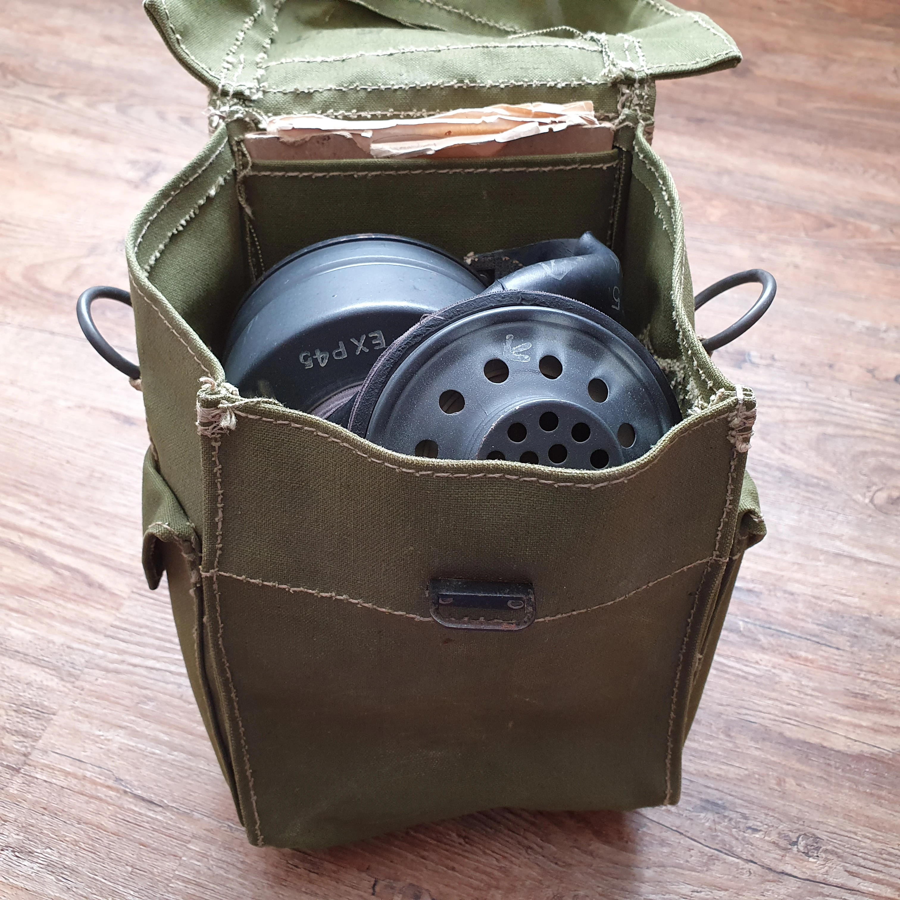

Demonstration of a properly stored Light Anti-Gas Respirator Mk. V in the Light Haversack Mk. II
Following this, you may proceed as explained in the Light Respirator addendum to finally insert the facepiece into the haversack.
- Grasp the container in the right hand, valve guard towards the ground, forehead portion of the facepiece towards the body.
- Place the headharness inside the facepiece.
- Grasp the edge of the facepiece opposite the container in the left hand and bring it as tightly as possible over the container, holding it in position with the thumb of the right hand behind the base of the container and the finger on the edge of the facepiece.
- Place the facepiece in the haversack, forehead portion first, the valve guard towards the quick release tab and eyelet.
- Fasten the haversack flap.
Please note, this method of storage will permanently damage your masks. Please do not insert the Respirator into the haversack unless the Container is detached.
Carriage of the Light Haversack
The Light Haversack, whether Mk. I or II, was designed to be carried in three positions, some models designed specifically to favour one of the three. These three positions were named Belt Position, Chest Position and Slung Position.
Slung Position:
"When slung over the right shoulder, the haversack is on the left side of the body, quick release tab and eyelet away from the body".
This method of carriage is most famous for its use during Operation Neptune, the Normandy Landings and following mission. The slung position was possible to employed without the use of a string, as seen on earlier haversacks, however, it should be noted that on occasion, the Light Haversack Mk. II would be fitted with D-rings, suspended by short canvas tapes, with a tan or green string attached to one so that the man would have been able to secure the haversack to the waist better. It is unclear when/where these variants were issued, however, it is assumed they would have been created for those required to use the Slung or Chest Position.
Chest Position:
"When worn on the chest the sing is shortened until it will just pass over the head, quick release tab and eyelet to the front. The haversack should be high up on the chest, and, if further shortening of the sling is necessary, one of the sides of the sling should be detached and fastened, at a suitable position, to the sling, on the far side of the other slide. The chest position may be found suitable for transport drivers".
As with the slung position, the chest position could be employed without the use of a support string, however, as mentioned above, a limited number of Light Haversacks with a string were created, likely for this purpose. As mentioned in Appendix F, this position was mostly recommended for use with transport drivers and would likely have seen little use outside of this, except, perhaps, when risk of gas attack was high, thus using this position to double as the "alert position" used earlier in the war with the General Service Respirator.
Belt Position:
"When carried on the equipment belt, the haversack is secured at the rear by means of the two double hooks. The ring is detached and held inside the haversack by means of the canvas tape and press button".
This position appears to have been the most commonly employed and can be seen demonstrated by Parachute Regiments from both Britain and Canada. This method was likely the first to be operationally used and was used in this manner following the war.
Repair Producedure for Light Respirators
Information on the repair, sentencing, proof, replacement, etc., of Respirators, Anti-Gas, Light is detailed extensively in RAOC Part 8, Sub-Pamphlet No. 2 to Pamphlet No. 26. General instruction prefers that components are repaired before being marked B.L.R. (beyond local repair) and replaced. This was often something which was considered when designing the latter components of the Light A.G. Respirator. For example, Valve Holders Nos. L1 and L2 are unable to be repaired, however, the 1943 desiged L3 Valve Holder can be fully disassembled and repaired with ease.
This section will be split into components with details on how to replace or repair the parts and with what tools. Note that separate sections on the repair tools cannot be provided at this time due to a general lack of knowledge.
Replacement of Eyepieces
The replacement of eyepieces was incredibly crude in comparison to that of other components. Factory fitted eyepieces were attached using a component known as Clip No. 4 with a protective rubber sleve covering the screws. This clip, essentially a hose-clamp, was clearly unavailable at times and so, to replace the eyepieces, the use of two binding wires or wire ties would be employed. The wires would then be covered with 9,5 mm (3/8 inch) tape.
It is noted that the use of Clips No. 4 should be favoured if available, however, instruction on wire repair was there to prevent reliance on a more complicated component.
Replacement of Headharness
To begin with, repair technitions were made aware of the issue with the use of the L1 harness and dermatitis. As you may have noticed in the table at the beginning of this page, none of the DERM facepieces were fitted with L1 harnesses. This is because they have some rubber content which would cause irriation to the skin. The L2 harness is made entirely of canvas, and so it is important to ensure that no DERM facepiece is fitted with an L1 harness. Aside from this, there was generally no preference during the war.
Whilst L1 harnesses were able to be repaired, the documentation clearly states that L2 harnesses must be replaced. As for the L1, information on repair is unfortunately unavailable as it is included only in the entire compilation of Part 8 Pamphlet No. 26, the only one available to read being a Sub-Pamphlet. However, infomation here suggests that the elasticated webbing straps were made in different lengths based on the size of mask they would be fitted to, which would explain why some L1 harnesses, fitted on Large masks, are noticably longer.
Replacement/Repair of Valve Holders
Replacement of Container Mounts
Replacement of Inlet Valve
Replacement of Light Containers
Repair of Light Respirator Haversacks
Cleaning of Facepieces & Haversacks
Decontamination & Disinfection of Facepieces
References & Further Reading
- Special Light Respirator for Assault Troops: Protection Efficiency - Held by the National Archives, Kew
- Special Light Respirator for Assault Troops: Production - Held by the National Archives, Kew
- Special Light Respirator for Assault Troops: General - Held by the National Archives, Kew
- Regulations for Army Ordnance Services Part 8: Respirators, Anti-Gas, Light (Command of the Army Council)
- Gas Training 1942 & 1943 Addendum
- Advanced Gas Training 1943
- Photographs of Light Anti-Gas Respirators taken by and from the collection of Baroque4Days (myself)
- Various posts on the War-Relics Forum
- Various Document Descriptions from the British National Archives Record Search Site
- A British Army Contractor Log Book of unknown origin
- SECRET - OFFICIAL HISTORY OF THE SECOND WORLD WAR: Special Weapons and Types of Warefare Vol 1 - Gas Warfare, compiled by Lieutenant-Colonel D. J. C. Wiseman
- http://josephs-militaria-and-homefront-collection.co.uk - Info on P44 Web Equipment
- http://ibasecretariat.org/porton_down_rep_1989.pdf
- More info on 1950s issue of wartime respirators: https://www.youtube.com/watch?v=HvhSFcUZxRo
- Information on rubber and other companies: https://www.gracesguide.co.uk/Main_Page